Solutions & Technology
Author:
Ricky Rung

Author:
Earlier this year, a client came to Indesign with a system designed to heat probes to a set temperature. The system had been designed by another firm, but they were unavailable to continue, so the client approached us to investigate some issues they were having.
The system design included three microcontrollers. Let’s call them temperature, control, and display.
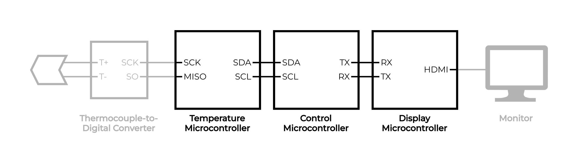
Note that the system actually monitors the temperature of four probes, but the diagrams show one for simplicity.
The temperature microcontroller is responsible for reading the temperatures from thermocouple-to-digital converters, the control microcontroller uses those temperatures to control outputs using PID controllers, and the display microcontroller is connected to a monitor to display the system state to an operator.
To work together, the three microcontrollers need to exchange information. For example, the control microcontroller needs to know the current probe temperatures to know how to adjust the outputs, and the display microcontroller also needs to know the temperatures to display them on the monitor.
To accomplish this, the three microcontrollers communicate using several protocols. The control microcontroller leads the communication and commands the temperature microcontroller via I²C and the display microcontroller via UART.
As this system was new to us and quite complex, we decided it would be helpful to first watch the data flow through the system as a third-party observer using a logic analyzer. Adding logging to the three microcontrollers could also work, but some of the microcontrollers did not have a port for log output, and adding logs risks affecting operation. The time it takes to print log messages can throw off timing, causing system behavior to change.
To observe the system without influencing it, we connected a logic analyzer to each of the interfaces and monitored them during a procedure. We left the firmware unchanged for these initial tests.
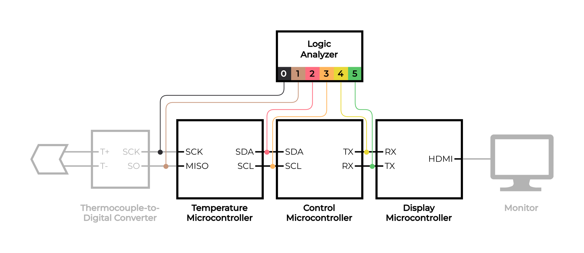
The logic analyzer allowed us to see the temperature readings as they entered the system and passed from microcontroller to microcontroller.
The temperature readings entering the system from the thermocouple-to-digital converter come four bytes at a time over a SPI interface.
For example, here’s the first temperature reading.
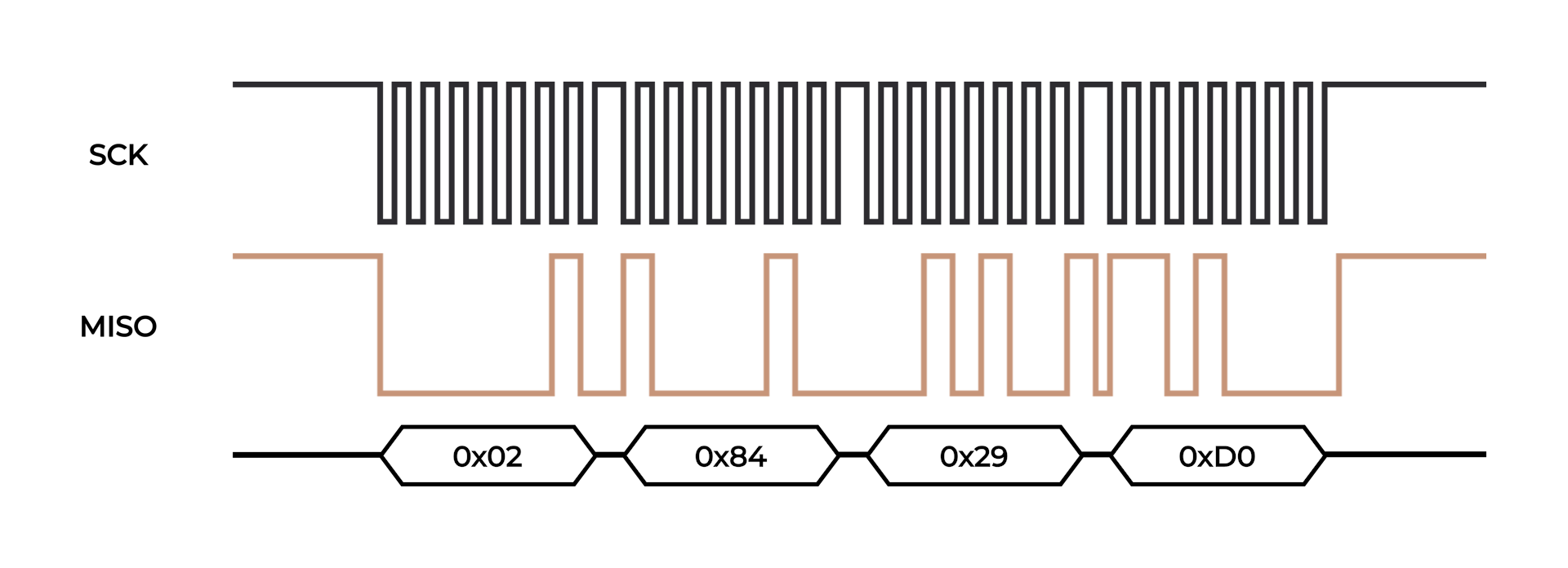
The temperature itself is the first 14 bits: 00000010100001 = 161, in quarters of a degree Celsius, so 161 ÷ 4 = 40.25 °C.
While the logic analyzer software can decode the bytes exchanged over SPI, it cannot take the next step of turning those bytes into temperatures. It can, however, export the raw bytes to a text file. So, if we had a script that could take that file, split it into four-byte reads, find the first 14 bits of each, and output them as temperatures to a new file, we could then plot the temperature over time, as read directly from the thermocouple-to-digital converter.
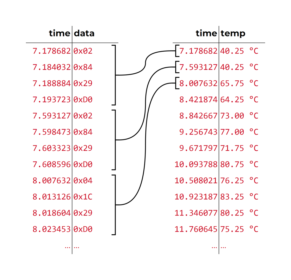
We decided this would be a good use case for AI code generation, so we gave an AI model the following prompt:
Write a Node.js script here that takes a single argument, a filename.
Open that file and parse it as a CSV with two columns: time and a hex byte. Skipping the header row, take four rows at a time and combine the hex bytes into a single 32-bit value, big endian. Then, take the upper 14 bits of that value and interpret them as a two’s complement temperature value in 0.25 °C increments.
Output a CSV file with the same name as the input, but with
-processedadded before the extension. Soinput.csvbecomesinput-processed.csv. The output file should contain a header row,time,temperature, and a data row for each four rows of the input. Thetimeshould be the time of the first row of each four-row block, and thetemperatureshould be the value in degrees Celsius found above.
The script it generated worked perfectly. With the conversion complete, we could produce a plot to see how well the system was controlling the probe temperature.
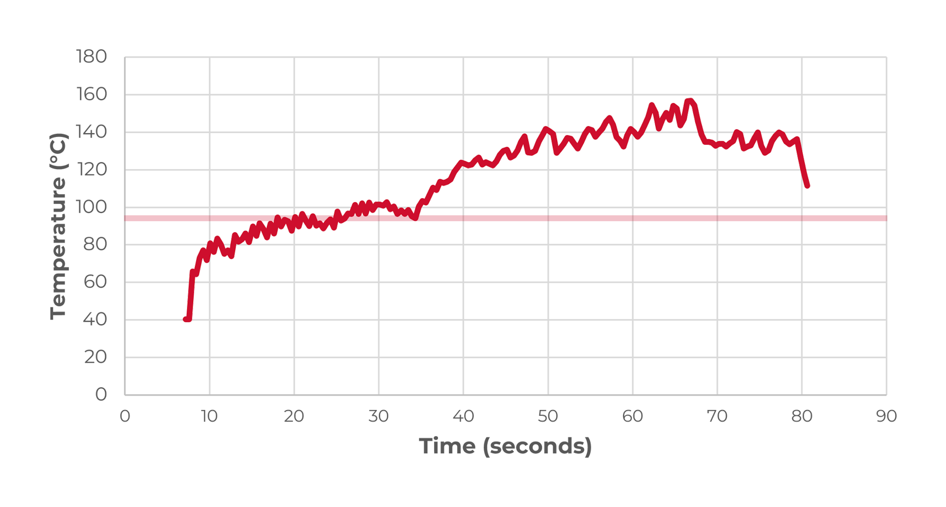
In this plot, the horizontal line is the target temperature. At around 35 seconds the temperature begins to rise well above the target.
To better understand what was going on, we followed a similar process to extract the temperature at the two other interfaces in the system. As these were custom command-response interfaces that relayed more information than just temperature, their scripts were more complex. Nevertheless, the AI, given details of the protocol, was able to generate working temperature extraction code for them as well.
Finally, we had a clear picture of a probe’s temperature as seen by all parts of the system, and the issue was immediately apparent.
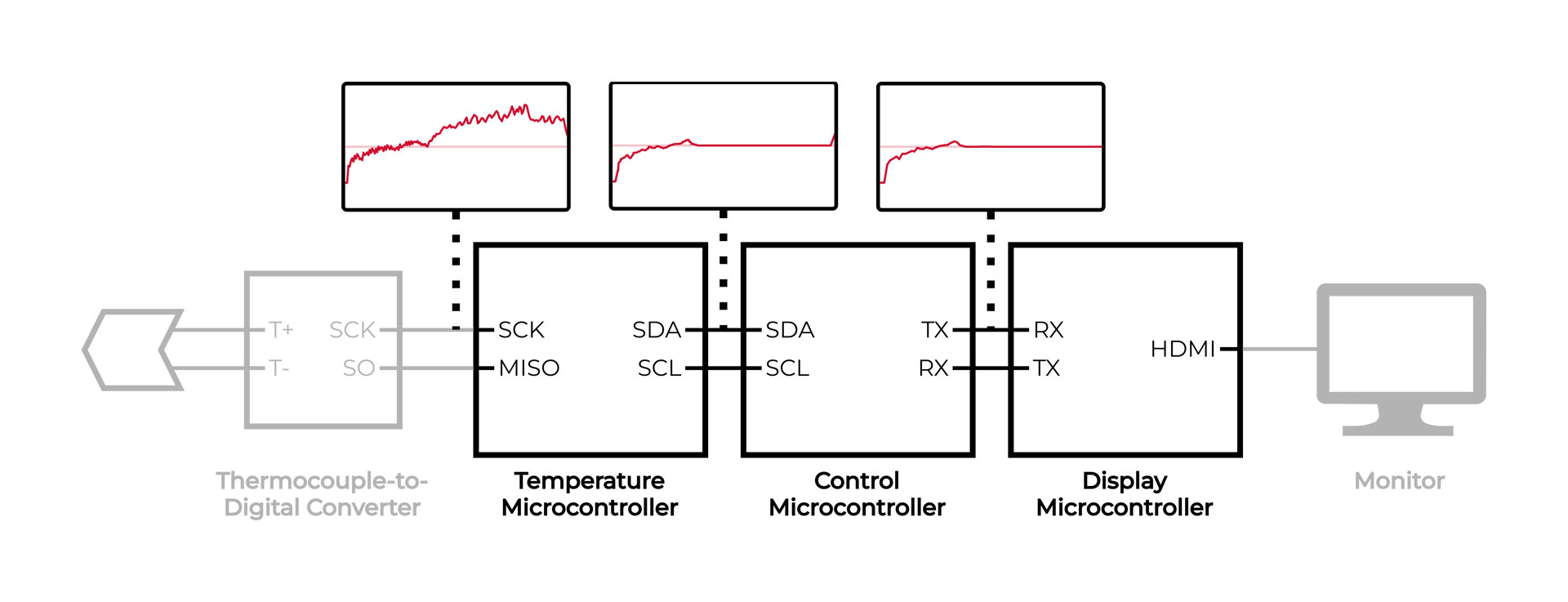
In the plots above, the horizontal line is the target temperature. The true temperature, as read from the thermocouple-to-digital converter, greatly exceeds the target. But the temperature microcontroller hides this, presenting a nominal temperature to the rest of the system.
The control microcontroller drives the output, and it is not receiving true temperature data, so it cannot keep the temperature under control. The display microcontroller displays the temperature on the monitor, and it is also not receiving true data. The temperature on the monitor appears normal, and the operator is unaware.
At this point, we felt we had what we needed to dive into the code.
The previous design firm was attempting to resolve an issue caused by spurious temperature readings. The system generates an error and stops the procedure when the temperature exceeds a high temperature threshold, but sometimes the temperature read fails and erroneously returns a high value. For example, the temperature readings may be 80, 80, 140, 80… As the readings are taken 400 ms apart, and the temperature cannot change that fast, the 140 is in error, but it would still trigger the fault and stop the procedure.
So, they added a glitch filter that would ignore up to two high readings before triggering the error. The error would still occur within about one second of true high temperatures, which was sufficient to ensure safe operation.
But the code has a flaw.
bool isTemperatureValid(int temperature, int probeIndex)
{
    static uint8_t highTempCount = 0;

    bool acceptTemperature = true;

    if (temperature > HIGH_TEMP_THRESHOLD)
    {
        if (highTempCount < 2)
        {
            highTempCount++;
            acceptTemperature = false;
        }
    }
    else
    {
        highTempCount = 0;
    }

    return acceptTemperature;
}
Recall that the system manages four probes. When reading temperatures, it does so in sequence: after reading temperature 1, it reads temperature 2, then 3, then 4, then back to 1.
The code above counts the number of high temperatures it sees in a row but does not consider which temperature is being read. Therefore, if some probes are overheating, but not all, it can suppress those high temperatures indefinitely.
For example, if probes 1 and 2 are cool, but 3 and 4 are overheating, it will see the high temperature on probe 3 and increment highTempCount to 1, and the high temperature on probe 4 and increment highTempCount to 2. But, when it goes back to probe 1, it sees a normal temperature and resets highTempCount to 0. This pattern repeats, so the counter is always reset before it ever reaches the error condition, and all high temperatures are ignored.
The consequence is that the temperature microcontroller hides high temperatures from the rest of the system, preventing the control microcontroller from taking them into account as it controls the outputs and generates system errors. As the display microcontroller receives its data from the control microcontroller, the high temperatures are also hidden from the operator.
The fix to this issue was to consider only consecutive readings of the same probe when applying the glitch filter. But, even with the issue fixed, the logic analyzer and processing scripts remained useful.
After patching the code to resolve the issue, we used the logic analyzer to capture data from the system over many procedures to verify the fix. As the logic analyzer is separate from the system, it does not affect its behavior but still provides a clear window into system operation.
Having access to the readings directly from the thermocouple-to-digital converters was perhaps the most useful. Since these readings are unprocessed by the system firmware, they are the best source of truth aside from using an external temperature probe. By monitoring these values, we can see how well the firmware is keeping the probes at the target temperature.
After the fix, across many scenarios, the unexpectedly high temperatures no longer occurred, and all probes were kept close to the target temperature for the duration of the procedure.
Indesign, LLC is a multi-discipline engineering design firm that specializes in full turnkey electronic product development. From concept to manufacturing-ready design, our team provides end-to-end product development with a strong focus on quality, efficiency, and innovation. With an ISO-certified development process and a proven track record of success, we help clients bring new products to market quickly and reliably. We provide electrical, RF/wireless, embedded software, mechanical design, and more!
Ready to get started? Contact us today at 877-561-0274 to discuss your next project!